Adjustable timer circuit using 555 555 timer tutorial: how it works and useful example circuits View block diagram of ic 555 timer gif
555 Timer Basics - Astable Mode
Astable multivibrator using 555 timer The history of 555 timer ic Monstable multivibrator using 555 timer
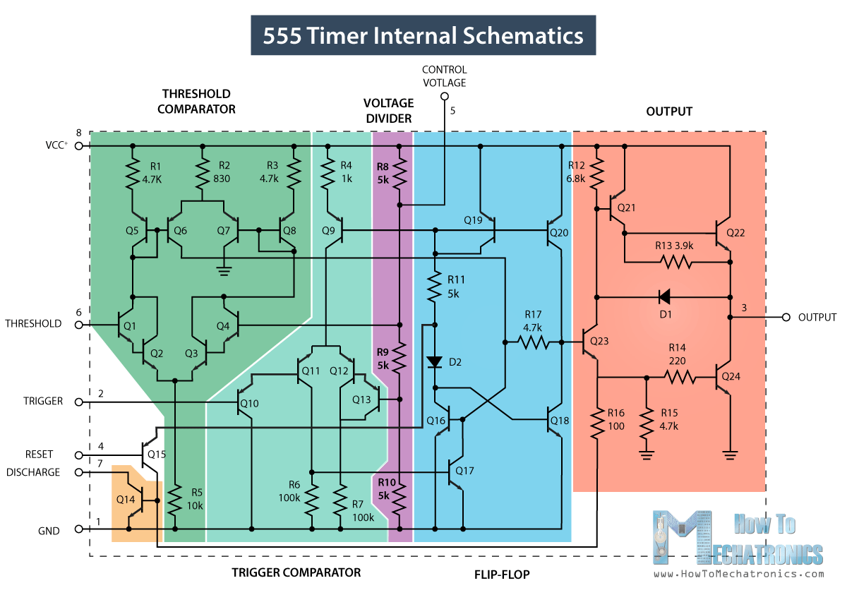
555 timer diagram block circuit chip does ne555 datasheet inside works work eleccircuit pinout look function
Adjustable timer circuit using 555Introducing 555 timer ic 555 timer astable led mode flashing photoresistor circuit resistor capacitor light basics circuitbasics diagram blinking using potentiometer flash ohm makeHow to make a 555 timer.
555 timer ic-block diagram-working-pin out configuration-data sheet[diagram] 555 timer chip diagram 555 astable timer circuit multivibrator diagram using oscillator diode circuits voltage regulator input555 timer circuit multivibrator diagram monostable schematic astable lm555 unstable.

How does ne555 timer circuit work
555 timer circuit ic diagram astable mode tutorial introducingDraw the pin diagram of ic 555 Ne555 timer pin diagram555 timer circuits blinking component.
555 timer diagram ic block chip transistor tutorial discharge multivibrator does circuit logic electronics flop flip monostable bistable mode projects555 timer basics 555 timer diagram ic block circuit ne555 controller configuration working op pins flop flip pwm discharge electrical resistive555 timer basics.

Introduction to the 555 timer
Introducing 555 timer ic555 timer circuit using light dancing circuits diagram easyeda chip pcb pulse 555timer ne555 projects electronics time astable lm555 mode Timer circuits555 timer ic.
555 timer ic ne555 eleccircuit does pinout frequency using datasheetHow does ne555 timer circuit work Inductor-based astable 555 timer circuit555 timer circuit ic diagram astable mode tutorial random introducing.

555 timer ic pin diagram features and applications
How does ne555 timer circuit worksDancing light using 555 timer 555 timer tutorial555 timer ic diagram dual history ics invention story.
Timer 555 circuit diagram schematic ne555 datasheet discrete kit pinout block does circuits transistor works eleccircuit integrated functional pins connectionFm generation using 555 timer 555 timer monostable circuit diagram variable shot mode led pulse resistor potentiometer basics off time use bistable connect simple clockHow does a 555 timer work?.

555 timer fm using generation circuit diagram circuits signal control electrosome multivibrator voltage
Set 2x e351d y 2x e355d timer ics gdr hfo envío mundial rápido el555 timer circuit electronics lambert .
.


Introducing 555 Timer IC - Tutorial | Random Nerd Tutorials

555 Timer Basics - Astable Mode

555 Timer IC - Working Principle, Block Diagram, Circuit Schematics

Introducing 555 Timer IC - Tutorial | Random Nerd Tutorials

Draw The Pin Diagram Of Ic 555

Inductor-based astable 555 timer circuit - handla.it

How To Make A 555 Timer